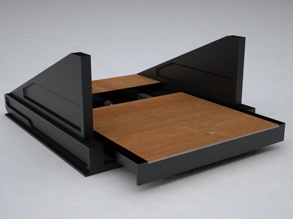
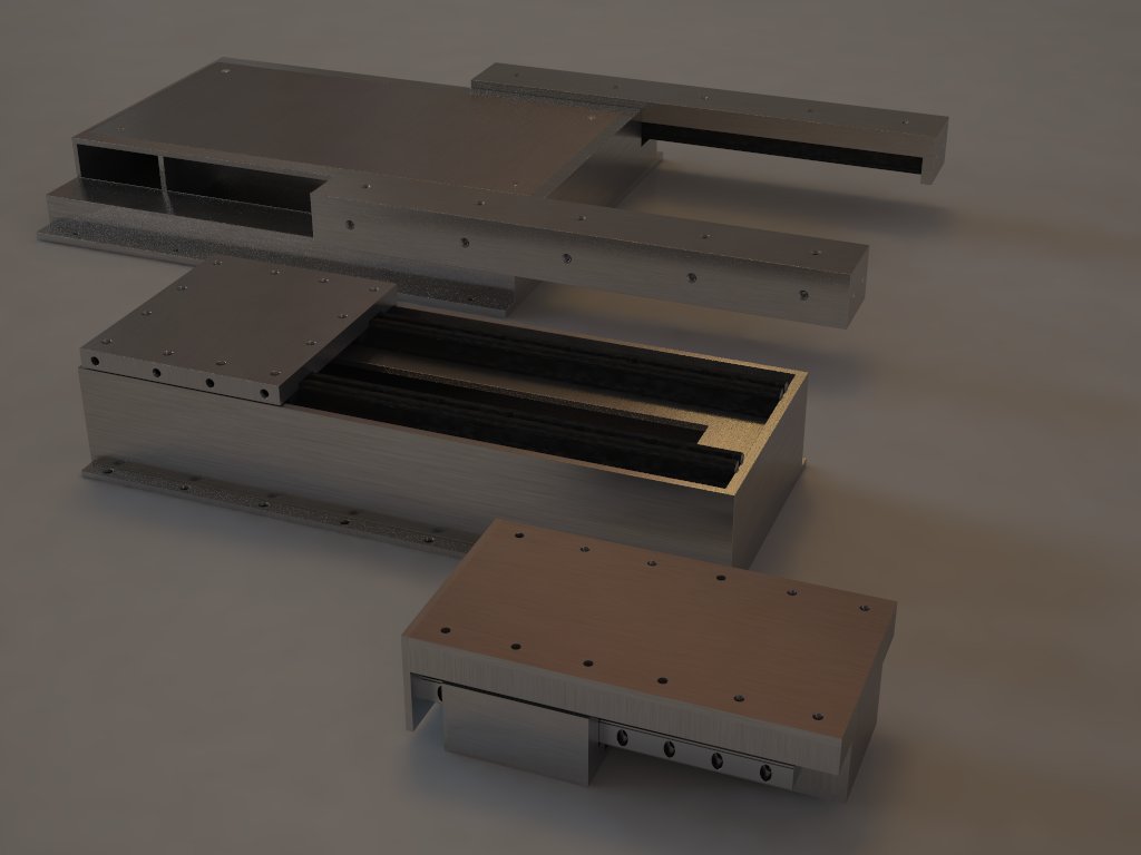
 All the boxes rendered: 1 box per axis. Each box can be lengthened to upgrade your CNC without having to buy an entirely new machine.


 Here are pictures of the final proof-of-concept prototype model of Concept 3. This is where I ended my first semester of my school project. It is a fully functional 3 axis CNC machine. It's setup at about 120 inch per minute, and an accuracy of about 0.015" I used a floor engraver setup configuration as supposed to a typical desktop CNC configuration. In this setup I am capable of doing CNC work on the surface below which I demonstrated during my end of semester presentation. Built time: 1.5 weeks
 From the end result of the full scale materials testing, I decide to go back and rethink some parameters. Concept A's main idea is to have the X axis to be relocated from top of the machine to the front of the sliding tray. This will enable the user to use it as either a standard CNC or as a floor mounted engraver to do CNC work below the surface, much like Prototype 2. After contemplating this, I believed I was still limiting the users by setting specific arrangements. What if the user wants to rearrange it in some odd way, they would have to do permanent modifications for that to happen. Though Concept A is still a big step from production CNC machines, it is still limiting on what arrangements it can perform.
 The original idea I had was to make a sleek looking CNC, something modern that doesn't make it look like an industrial-look cold aesthetics as most CNC have. Here are some of my early renderings and concept development.


 This was a good thing as it made me rethink the entire project. As this was my class project we have to consider the audience, who is this marketed for. It got me thinking that only a small percentage would actually need/want a super light weight CNC and would be willing to pay the premium for it. It made me rethink why was I using space-age composite materials. This would be the first eureka moment in my project...

 I did multiple experiments to see how many layers of kevlar I need and ways to make it stiffer without adding added weight. By adding ribs or using sandwiching techniques, I was able to make it rigid and light.
 By this time, I am starting my final year in my Industrial Design degree. Since I always wanted to update my CNC with better improvements I decided to use it as my grad/thesis project. My original intent for the project was a portable CNC that is multi-functional/transformable to allow CNC technology to progress (as I believed CNC technology has had very little progress in the past decade).
 Bearings and slides are now all fully supported. X and Y axis are using 24" Thompson bearings/slides while the Z axis is by another brand (bought separately). Motors and control boards are the same Xylotex setup from my old setup.