Apr 25, 2010

Rendering

Vertical wall plotter configuration allows for custom designs to be plotted directly on walls, a new exciting alternative to wallpaper


wheeled-cart form and it's boxes and components all laid out

As seen on:

As seen on notcot.org


RedBlueCNC renderings

The physical model is painted and assembled.  The 269oz stepper motor isn't strong enough to pull the Z axis accurately so that will have to be upgraded soon.  There's minor backlash while the Y axis is fully extended, so will figure out a way around that.  A pulley system to keep it in-tension all the time should do the job, hopefully.  I haven't had the time to take pictures of the completed physical model yet as I'm one of the main people preparing for the exhibition show.

If you happen to be in Vancouver, the show is open to the public for free.  Opening is on May 1st and remains open for 2 weeks.  More information here:
http://www.ecuad.ca/about/events/42575

In the meantime here are some renderings done for my exhibition infographics.

Surface engraver


 The future laser-thingy tool-head upgrade

Apr 5, 2010

RedBlueCNC: model progress

The actual model building is going well.  The majority of the welds and drilling has been made, the X axis is operational and needing minor welds to make the Y and Z axis automated as well.  Hopefully by the end of this week everything will be ready for paint.  Final renderings hopefully will be started, as well as the exhibition display table I'll be custom building specifically for the CNC.

In spite of the time crunch, I have decided to make the rotational adapter to make the cart concept fully functional.  The rotational adapter will add some needed height as well to allow more clearance of the Z axis from the surface (estimating 8"-10" total clearance from surface to the bottom of the Z axis).  Added height can be easily accomplished by various measures as well.

I'm using 1/4" aluminum for the majority of the build.  It is a little heavier than expected but still not as heavy as most production CNCs out there.  Estimated overall weight about 60lbs.  Overall dimensions about 24" wide x 36" depth (side arm supports) x 24" height.

RedBlueCNC: renderings


Some renderings done for a mid-semester presentation.  Top picture shows typical use as a CNC router. 
Typical setup next to its cart form.
Pictures show attaching a waste board bed where stock materials can be mounted on.  In this configuration the CNC can be used as both desktop CNC and floor CNC without having to rearrange the boxes.


Picture shows the sequence to transform from cart to CNC.

toolheads: plastic extrusion = 3D pinter

Early this year I bought myself a plastic extrusion head (plastruder) from Makerbot.  It is fully assembled and ready to go but unfortunately I don't have time to mess around with it until the semester ends.  Having the hardware talk to my current software is the tricky part, it is usually plugged directly to its own open-source CNC control board with its own open-source software.  But since I already have a CNC control board, their software does not work with my control board nor my software does not talk directly to their hardware.  There are a few work-around I've been reading online, the main one by using a Linux-ran software.  This territory is fairly unexplored in the hobby scene so not too many information is available yet.  As I don't have time messing with software, this tool head project will have to wait. 

RedBlueCNC: more concepts

Here is my ideal concept for the wiring.  A simple flush mounted plug similar to a USB located on 2 sides on each box.  There are 2 locations specifically because if the user prefer to mount the box on the side where the wire would come out from, then it would cover the plug. 

But in the prototype world (real world), I don't have time in making a new plug so will be using a DB9 serial port plug similar to many hobby CNC setups.

One day I came across another idea of making it more portable.  If the boxes all pivot onto itself, it can be neatly stacked vertically in an organized manner.  Relocate the side support arms and attach a handle and wheels, now you have a cart in which you can easily carry your CNC anywhere!

The rendering also shows all the main components of the CNC package.  In which case the user, if preferred, can easily arrange the boxes or build a custom frame to specifically suit their purpose.


This rendering shows an upgraded concept of my wall-CNC setup.  The side support arms are flipped to allow closer access to the wall.

random renderings

Just some renderings I've done for fun.  This one is if all the pieces are clear acrylic.

Renderings of the main bearings and slides (Thompson).  A total of 4 of these are being used, 2 each per X and Y axis
Rendering of the Z axis slides/bearings being used.  I think their NHK bearings.  Though these are a lot smaller, they weight almost twice as much as the Thompson since they're entirely made of steel.  The Thompsons are mainly aluminum with a small track of steel where the bearings ride on (pretty nice design).

RedBlueCNC: specs and dimension

Since Concept 3's internal design for the Y and Z axis was working fine, I decided to continue the internal design for the RedBlueCNC (concept 4).

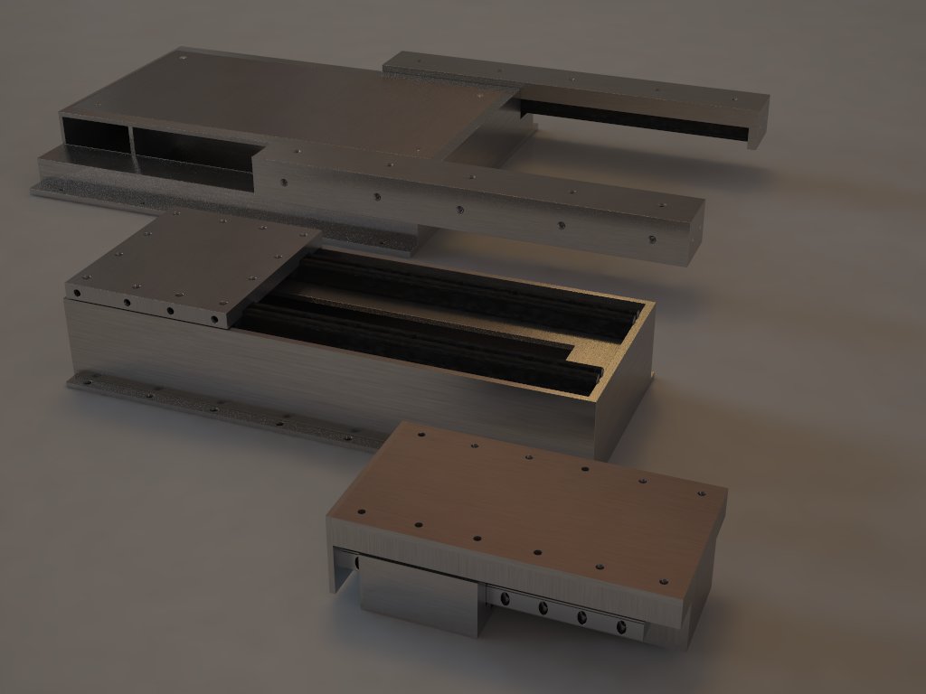
There are 3 main pieces for the box:
1) the top (where most parts attaches to)
2) the bottom (access cover for the mechanics)
3) the tray (not pictured)

Here is the finalized design, about 8" x 6" x 22".  The Z axis will be 18" long as the slides I bought are shorter length.  Each box can technically be as long as the user desires to be easily upgraded.  The top part is proposed to be aluminum extruded.  The bottom part will not be financially feasible to be fabricated out of extruded aluminum so am proposing it to be hand welded since it "would" be a limited scale production.  Ideally a strong plastic extrusion version could be made for entry level CNC or for those not needing stiffness (3d printing, etc). 

Cutting area is about 12" x 12" x 8" depth.  I purposely chose this size as (a) most designers and model makers would be able to do most at this size, (b) keep the size down as most people don't have room for larger tools, and (c) keep costs down for my prototype as I am a student still.  But as mentioned it can technically be lengthened to larger size easily.

Enter the RedBlueCNC

I really liked the new path I was going with but felt that something was still missing.  I knew Rietveld has done many important pieces of furniture, one of his most famous being the Red Blue Chair.  This is a very important piece is the history of design.  I decided why not combine both of his pieces together (the L40 light and the Red Blue Chair) as a nod to the history, and incorporate them into my CNC...


The RedBlueCNC
As tools are usually kept in the garage, they all usually have the same cold aesthetics.  Not everyone has room to keep larger tools like CNCs in a permanent location.  One of my main original problems I wanted to address with this project is to upgrade the aesthetics of a CNC machines so users would feel comfortable in leaving it exposed in their living room instead of keeping it in storage when not in use.  What if the tool can look as good in the center of your living room like a piece of art? 

Prototype #4: Development & Inspiration

As I developed the universal box design, trying to make a sleek frame to encase/complete the machine has been a hard task.  No matter what the boxes can't be any smaller so the frame had to be bulky.  That's when I decided to look for inspiration to some of my favorite design movements.  I took a trip to Dessau, Germany last summer and visited the Bauhaus building so the Bauhaus movement was still fresh in my minds.  Bauhaus has been one of the major influences in modern design, many important furniture has came from it.  Chances are if you've been to any museums, galleries, or art school you've most likely have seen on of the Bauhaus furniture.

Always enjoying the Bauhaus minimal approach in design, I looked towards it for inspiration.  This is when I rediscovered Gerrit Rietveld's L40 light fixture.  But Rietveld was not technically part of the Bauhaus movement but part of the De Stijl movement, which was influential to the Bauhaus manifesto.

This was an important turning point in my project development.  I was making the project more complex than it needed to be.  Instead of trying to hide the axis, I should embrace it and show it for what it is.  Rietveld's L40 light is exactly that, 3 lights in 3 axis.  Minimal, simple.


This was my newest direction, keep it simple and show it for what it is: 3 boxes in 3 axis.  This is an early rendering development of the new direction.  Side legs were needed as I found out from the wooden Prototype #3 model was front heavy, so side supports were needed to keep the machine from tipping over when the Y axis was in full reach.

Prototype #4 (RedBlueCNC): The beginning of the RedBlueCNC

As I entered the second semester of my year long grad project, I looked back where I left off from Prototype #3.  There were some issues I know I had to deal with:

1) I was not totally satisfied with the aesthetics.  Because I decided to encase each mechanical axis into its individual box, the boxes ended up being large in which the outside frames had to be bulky as well.  I couldn't minimize the frame size into a sleek compact form. 

2) There were too many boxes.  I had to simplify the box designs to simplify (in a "what if" scenario) and reduce the costs of production.  Which means I should use only a single box design for all axis.  Also mounting holes had to be universal, so any box would be able to fit any other box in any direction.

Here is my 1st concept rendering of the universal box for all 3 axis.  Mounting holes every 3.5"  Size was made based on my bearing sizes in which I wanted 3 mounting holes across for each sliding tray.  I eliminated the bottom lip of the box too allow it to be mounted on its side if wanted.  Instead the end-users can easily make their own angle brackets.

Prototype #3: Alternative Model Renderings

As the boxes are removable, people would be able to rearrange them to suit their specific needs.  Here are some rendering concepts in which I came up with for Prototype 3.

Floor CNC concept.  My wooden proof-of-concept prototype is setup in this configuration.  The idea here is the machine is setup specifically to do floor engraving.  You can take the machine to over sized materials that would be otherwise impossible to CNC; like hardwood floors (as pictured), table tops (to do inlays), concrete sidewalks, etc..  Replace the router tool-head with a laser or ?? to further do explorations.

Wall CNC concept.  This will allow the machine to create custom patterns directly on the wall eliminating the use of wallpaper. 

My "Thank You" rendering.  This is where I left of my first semester of a year long project.  The second half is the exciting part in which where I believe I really was able to push CNCs in modularity, and aesthetics.

Prototype #3: final renderings

Here are some renderings I used during my end of semester presentations.  Top picture is the cutaway view to show the internal setup of the X axis.

All the boxes rendered: 1 box per axis.  Each box can be lengthened to upgrade your CNC without having to buy an entirely new machine.

The proposed deluxe starter kit will have 3 boxes and a basic CNC body kit in which the user can assemble in a few hours.  Not people are capable in making a CNC machine in a short period of time.

Assembly is simple:
1) bolt the parts onto the X tray box, slide the box into the CNC frame


2) Bolt the Y axis into the frame
3) Attach the Z axis onto the Y axis
4) attach your desired tool-head, in this case a hand router

You now have a desktop CNC machine!

Prototype #3: final prototype


This is insides of the Y axis prototype, Z axis is similar as well.  The build is rough as it is only used as a proof of concept.  The final material will be out of aluminum. As you can see the mechanics is simple: motor turns screw, screw turns nut, nut moves tray.


Here are pictures of the final proof-of-concept prototype model of Concept 3.  This is where I ended my first semester of my school project.  It is a fully functional 3 axis CNC machine.  It's setup at about 120 inch per minute, and an accuracy of about 0.015"  I used a floor engraver setup configuration as supposed to a typical desktop CNC configuration.  In this setup I am capable of doing CNC work on the surface below which I demonstrated during my end of semester presentation.  Built time: 1.5 weeks

Inspiration: CNC related links

Some links I have bookmarked that may help some people:
http://makerbot.com/ DIY 3d printer
http://reprap.org/ DIY 3d printer (makerbot is based off of)
http://www.iaacblog.com Institute for Advanced Architecture of Catalonia blog, lots of CNC projects
http://replicatorinc.com/blog/ 3d printer blog
http://blubee.com/theblog/?cat=50 Art-based robot blog
http://www.nilsvoelker.com/content/_pages/robotic.html tech-based artist's page
http://www.adafruit.com/blog/2009/04/27/peter-sands-plant-fasting/ plant farming CNC
http://www.contraptor.org/ open source hardware (parts to prototype CNCs, etc)
http://www.makerbeam.com/pledge.html same as above
http://candyfab.org/ sugar-based 3d printer
 http://blog.makezine.com/ Make magazine's tech-based blog

Inspiration: CNC art

And here are some experimental CNC created art.  I had these saved for awhile so can't remember any of the artists names nor links, sorry.


Inspiration: Other CNCs


Before I continue I should mention some of CNC related technology I use for inspiration. 1

1) table top engraver by an ID student project
2) wheeled CNC plasma cutter? concept
3) hexapod spider CNC
4) robot brick layer
5) parallel robot CNC